![]()
CONSULTANT & CONSTRUCTION
欽總工程股份有限公司
台北市110信義區永吉路179號12樓之1 TEL: 886-2-8787-8763 FAX:886-2-8787-8651
www.cceng.com.tw


|
CONSULTANT & CONSTRUCTION欽總工程股份有限公司 台北市110信義區永吉路179號12樓之1 TEL: 886-2-8787-8763 FAX:886-2-8787-8651www.cceng.com.tw
|
|
|
INSTALLATION, OPERATION & MAINTANANCE MANUAL FOR DIOXIN REMOVAL CATALYST
C.K.S AIRPORT INCINERATION PLANT
content 1. GENERAL *1.1 Introduction *1.2 Dioxin reduction *1.3 Catalyst description *1.4 Catalyst poisoning *
2. DIOXIN REMOVAL SYSTEM DESIGN *2.1 Design condition *2.2 Expected performance *
3. CATALYST SPECIFICATION *3.1 Catalyst data sheet *3.2 General catalyst handling *3.3 Catalyst safety data sheet *
4. CATALYST INSTALLATION INSTRUCTION *4.1 Handling procedure *4.2 Handling precautions, MSDS *4.3 Packing *
5. CATALYST STORAGE *5.1 Storage procedure for SINOX Catalyst *5.2 Storage procedure for SINOX Catalyst *
6. LAY – UP REQUIREMENTS *6.1 Cleaning *6.2 Temperature and Humidity *
7. INSTALLATION AND REMOVAL INSTRUCTIONS *7.1 Installation Procedure for SINOx catalyst module *7.2 Sequence of operations *7.3 Installing catalyst modules *
8. OPERATING PROCEDURES CONSIDERING CATALYST REQUIREMENT *8.1 Catalyst Operation *8.2 Shutdown *
9. SPECIAL ITEMS *9.1 Fly ash deposits / condensation on catalyst *9.2 Combustible gases upstream of the catalytic converter *9.3 Catalyst cleaning procedure during shutdown (if required) *9.4 Required condition *
10. LOGIC DESCRIPTION *10.1 Start up procedure *10.2 Stop procedure *10.3 Temperature control system (inlet catalyst) *10.4 Soot blower system *10.5 DeDioxin catalyst bypass system *10.6 Catalyst stand by heating system *
The installed catalyst type is for high efficiency Dioxin removal. To achieve the best results, the catalyst is installed after the Bag Filter. In addition hot air is used to heat up the flue gas after Bag Filter from 160°C up to 203C. These additionally increase the performance of the catalyst. After the catalyst, the ID fan is installed to compensate the pressure drop of the total incinerator system. In addition, the Catalyst system is installed with a bypass to prevent catalyst or plant damage in case of malfunction. Also a heating system for cold start or for stand by operation is foreseen. All these measures ensure a optimum function of the Dioxin Removal Catalyst.
Organic traces are reduced by catalytic oxidation. The catalyst decreases the necessary reaction temperature down to 150 - 350 centigrade. Because of the high required removal efficiency, a minimum operation temperature of 200°C is required. Dioxin and Furan compounds are reacting to CO2, H2O, and HCl. The Dioxin Removal Catalyst has been modified to improve the PCDD/F removal efficiency. An example of Dioxin and Furan reduction is given the following
C12HnCl8-nO2 + (9+0.5n)O2 + (4-n)H2O Þ 12CO2 + (8-n)HCl C12HnCl8-nO + (9.5+0.5n)O2 + (4-n)H2O Þ 12CO2 + (8-n)HCl
The catalyst is designed and manufactured as a rectangular ceramic honeycomb with a standard cross-section of 150 mm x 150 mm in various honeycomb pitches, lengths and compositions to suit the specific application. This is a solid catalyst, i.e. it is homogeneous and consists of active catalyst material throughout. For use in practice in dust-containing gases, this means that the catalyst does not lose its activity as a result of surface abrasion. The individual catalyst elements are combined into modules. The modules are designed primarily with a view to permanently ensuring an operationally suitable arrangement of the catalysts in the reactor. At the same time, however, they also serve as transport containers. The module consists of a sheet metal shell, whose underside is provided with a support grate for carrying the catalyst elements. The upper side is in most cases provided with a simple grating which allows access. Depending on the particular use, a fine-mesh stainless steel net can be applied to this grating to protect the catalyst from foreign bodies or dropping dust deposits. In the module, the elements are sealed from one another and from the module housing by elastic seals consisting of mineral fibre mats. The catalyst essentially consists of titanium oxide (TiO2) in the anatase crystal modification, tungsten oxide (WO3) and vanadium pentoxide (V2O5) as the active component. The catalyst is stabilized by the composition and manufacturing process, i.e. a crystal transformation from the anatase modification of TiO2 into the more stable but unwanted rutile modification is inhibited at normal operating temperatures. The use of titanium oxide makes the catalyst also suitable for the treatment of flue gases containing acidic components (e.g. SO2/SO3, HCl, HF) etc. The porous structure of the catalyst material and its large internal surface area are critical for the catalytic properties. As a result of these properties, the phenomenon of capillary condensation could occur. The lower operating temperature of the catalyst is determined by the flue gas composition and the required removal efficency, while the upper operating temperature is governed by the crystal transformation already mentioned above, and also by sintering processes.
Over its lifetime the catalysts experiences a certain deterioration of activity. This is attributed to clogging of the pores of the catalyst with dust and to the transformation of the substrate material anatase to rutile at high temperatures. Earth-alkaline compounds are blocking the catalyst pores mechanically. The main problem is the formation of gypsum in the turbulent zone. Therefore concern about concentrations of Calcium is necessary. Alkaline-compounds, sodium and potassium, are penetrating the catalyst pores by condensation during a long-term stop of the plant. This leads to a chemical deactivation. Heavy metals are accumulated on the catalyst surface. In addition they are sintering at temperatures of 300 to 350 centigrade, which leads to a loss of active catalyst surface. Especially the presence of arsenic compounds, phosphor and mercury is to be limited. Plugging of the catalyst can occur by dust accumulation on the inlet of the catalyst. This accumulation is decreasing the number of passed catalyst cells. Besides decreasing the active catalyst surface the pressure drop is increasing significantly (countermeasure: installation of soot blowers). All deterioration mechanisms mentioned apply to a SCR - plant as a tail end installation like C.K.S Incineration Plant only to a rather negligible extent, but can be relevant in case of passing certain concentration limits in the flue gas composition and temperature.
2. DIOXIN REMOVAL SYSTEM DESIGN
The Dioxin Removal Catalyst system is designed for the following design condition*3) according to the Heat & Mass Balance sheet provided from C&C Engineering. Values are for one Dioxin Removal System system. Total numbers of Dioxin Removal Systems are two units.
Remarks: *1) based on 11% O2 dry
The following table shows the expected performance of the Dioxin Removal Catalyst system:
Remarks: *1) based on 11% O2
dry
Catalyst type honeycomb type, based on TiO2 and V2O5 The catalyst can be handled without special
protective measures. After handling, it is advisable to wash your hands.
However, inhalation of catalyst dust is injurious to health. Therefore
the following procedure should be taken: The respiratory mask described in the safety data sheet as personal protective gear must be worn if dust evolution (catalyst dust) exceeding the indicated MAC value is to be expected during the work. The MAC value relates to pure V2O5, which is present in the catalyst only in a concentration of less than 5 %. Our experience suggests that such dust evolution is not to be expected in normal handling of the modules in which the catalyst elements are installed, since the catalyst is not subjected to any mechanical stress. However, different conditions apply if, for example when grinding apparatus is used, catalyst material is also ground off or catalyst dust is generated in other ways. In such cases, respiratory protection should be worn as a precaution. The catalytic and mechanical properties can be affected by incorrect handling. The respective information can be found in the following section. Attention is drawn to the fact that non-compliance with the above mentioned precautionary measures can cause the following irritations or injuries through catalyst dust or constituents (e.g. V2O5) respectively: -) irritation of the eyes and mucous membranes -) damage to health through inhalation / swallowing -) no known ecological damage is known at present -) if lager quantities of V2O5 get into lakes or rivers, it can be harmful to fish and plankton
3.3 Catalyst safety data sheet
4. CATALYST INSTALLATION INSTRUCTION These specifications cover the handling, packing and transportation procedures for SINOx catalyst elements or modules.
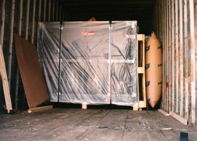
Shipping of catalyst and other supply items from the manufacturing plant to the construction site is partially by ship, train, or truck. Transport vehicles shall have air suspension and goods shall be covered with waterproof tarpaulins if the cargo area of the truck/trailer in question is not equipped with a weatherproof enclosure. Modules shall be secured to rule out the possibility of shifting in transit. Wherever possible, wooden beams and suitable padding shall be placed between modules for support purposes.
Catalyst Module in Container Applicable industrial safety regulations and company transport and safety procedures shall be complied with. The catalyst elements are contained in a steel frame, called a catalyst module, however both sides of the modules are open, thus exposing the catalyst elements to the atmosphere. Therefore the modules shall be handled with care to protect them from moisture due to rain, etc. Modules are delivered firmly attached to wooden pallets with steel straps. Modules shall only be stored in their original packaging and firmly strapped on pallets. The modules must be stored on the pallets on which they were supplied at all times. Due to the delicate nature of the catalyst, forklift operators must be instructed to use great care when lifting, transporting and setting down modules. The transport pallet must be centered on the forks and only lifted high enough to clear any irregularities in the road/floor. Use low gear and raise and lower load gently. Modules are completely wrapped in plastic sheeting, sealed with adhesive tape, and strapped to wooden pallets. For a limited time, this plastic sheeting protects the catalyst material against dust and moisture (rain, etc.), it is not to be considered waterproof over an extended period. If the catalyst material is to be stored for extended periods outdoors, (several days), e.g. during installation, additional tarpaulins must be provided. Plastic sheeting or packaging materials shall not be removed until immediately prior to installation.
Typical Transport of Catalyst Modules with Forklift Stepping or walking on top of the unprotected modules is prohibited. Catalyst modules shall be lifted only with a special lifting gear provided by others. The catalyst modules shall be handled carefully; mechanical shocks or must be particularly avoided.
4.2 Handling precautions, MSDS The catalyst modules shall only be handled in compliance with the Material Safety Data Sheet (2 pages). Please refer to chapter 3.3.
The catalyst modules/elements shall be covered for transportation with a waterproof covering with no tears or holes. Covering of the new catalyst is carried out in the Argillon catalytic converter shop under consideration of the particular transport conditions. Covering which has been removed shall be retained until it is certain that it is no longer needed.
Prior to installation the catalyst may have to be stored for short or long periods. Storage conditions are described in the following sections. If the customer fails to meet the following conditions Argillon will void the catalyst performance guarantee.
5.1 Storage procedure for SINOX Catalyst The following specifies the conditions under which storage of SINOx catalyst is possible for long periods without any change in the guaranteed properties. Honeycomb catalyst modules are delivered in a horizontal orientation. Honeycomb catalyst modules shall not be turned to a vertical orientation. The modules shall be stored in packed condition on the
transportation pallets. The original covering (typically a plastic
sheet) shall not be removed. The modules shall not be stacked. The floor space for storage should have an area at least as large as the corresponding reactor cross-section. The modules shall be stored indoors and protected from rain. The modules shall be kept free from oil or other chemicals. The modules shall be kept as dry as reasonably possible. If dry conditions inside of the catalyst wrapping can be guaranteed (similar to a warehouse: dry ground, closed doors, etc.) the catalyst modules may be stored in a container or tent (temporary warehouse) on site. The modules should be stored in a stable position on a firm and level floor. Storage conditions shall be checked regularly (monthly) and recorded to ensure conformance with the above conditions. Argillon reserves the right to inspect the storage area prior to catalyst delivery. If projects are receiving large amounts of new catalyst, where indoor storage is not feasible due to the space requirement, Argillon excepts outdoor storage for up to two (2) months. The conditions shall be as close to indoor conditions as possible, i.e. level ground, ground covered by watertight tarpaulin and catalyst modules completely covered by water tight tarp.
5.2 Storage procedure for SINOX Catalyst Catalyst, which has been exposed to fly ash and exhaust gas, must be stored under more stringent conditions than new catalyst. Catalyst deactivation may take place via leaching of fly ash constituents through moisture. Dew point conditions and frost formation must therefore be strictly prevented through the use of heaters or dehumidifiers if catalyst deactivation is to be avoided. Additional handling constraints will be necessary to minimize exposure of personnel to the exposed catalyst surface and fly ash. Please contact Argillon regarding specific questions on storage and handling of used catalyst and the resulting impact on catalyst performance guarantees.
During long term periods where the reactor is not exposed to flue gas, the properties of the catalyst can be preserved best if the catalyst is kept clean and dry as best as possible.
At the beginning of the lay-up time the reactor and catalyst should be inspected and manually cleaned (e.g. air blown/vacuumed) properly. This to remove the fly ash sitting on the catalyst surface. Fly ash should be removed carefully because ash constituents may cause chemical reactions with the catalytic material over the long time, which would deactivate the catalyst to a certain extend.
To avoid condensation in the pores of the catalyst and to inhibit chemical reactions with the remaining fly ash, the catalyst shall be kept on a temperature/humidity range as shown in the chart below. 
If the temperature in reactor is maintained above approximately 44°C, no active humidity control measures have to be taken. This temperature corresponds to 40% relative humidity assuming an originating wet bulb temperature of 28°C For temperatures above 10°C the humidity shall be below the curve
7. INSTALLATION AND REMOVAL INSTRUCTIONS
7.1 Installation Procedure for SINOx catalyst module This document covers the installation procedure for SINOx catalyst modules. It is general only, because the procedure depends on the site-specific installation concept. Detailed installation concept shall be provided by plant constructor. Preconditions for Installing Catalyst Modules Permit to work has been granted for the site. Details given in chapter3 and 4, especially the "MSDS" for the catalyst shall be observed. The following special tools are required for moving the modules: Module lifting rig Module turning device Hoist for transportation The following material should be prepared Catalyst modules are delivered covered (typically a plastic sheet). Remove the covering just before placing them on the turning device. Take care not to subject the modules to mechanical shocks, such as hitting against the structure during lifting. Do not install on a rainy day to prevent the catalyst from becoming wet. If unavoidable leave the cover on the modules as long as possible, i.e. until the modules are moved inside the reactor.
Always use a special lifting device
If a module is to be set down temporarily, place it on sleepers and cover it.
Verify that welding and grinding operations on module supports or flue gas ducts have been completed. Install and perform test operation of hoists, etc. Sealings must be in stock and prepared.
7.3 Installing catalyst modules The catalyst modules shall be installed in compliance with the following procedure: The catalyst modules are delivered in a horizontal orientation firmly attached to a wooden pallet with steel straps. They shall not be removed from the pallets until they are about to be installed/lifted to the installation level. The original covering (typically a plastic sheet) shall not be removed until they are about to be installed/lifted to the installation level. After the modules have been taken out of the warehouse they shall be kept stored in a rainproof area until they are about to be installed/lifted to the installation level. If the modules are to be temporarily stored in an outdoor area they must be covered with waterproof tarpaulins as the original covering is not sufficiently waterproof. The modules shall stand on solid level ground all times.
Installation Sequence: Modules shall be transported to the turning device by forklifts or trucks. Remove protective cover of catalyst modules (in rainy weather keep modules covered as good as possible) Modules shall be tilted 90° as depicted below
Two modules per layer are combined to form a large module (14x14 elements). Field welding per catalyst supplier’s drawing instructions shall be performed. Modules shall be transported to the hoist by forklifts or carriers Modules shall be lifted to the installation level by hoist (using a special lifting rig).
Figure -1 Placing the module Please note, C.K.S Dioxin Removal Catalyst module size and design is different as here depicted.
8. OPERATING PROCEDURES CONSIDERING CATALYST REQUIREMENT The below given procedures are based on the requirements ensuring that the catalyst is operated under optimum operating conditions and to protect it from adverse conditions. Almost all of them take place automatically. Other procedures and operating parameters will have to be added to procedures below in order to ensure safe operation of equipment not in the scope of supply of Argillon.
Start - up The condition of the catalyst is decisive for the startup procedure used. A distinction is made between cold, warm and hot starts. As the condition of the plant may not be identical with that of the reactor, depending on configuration and mode of operation, cold warm and hot starts shall be based on the current condition of the catalyst. The condition of the reactor described here is based primarily on the catalyst temperature and the resulting of moisture entrapment. Possible temperature extremes and gradients across the inlet area as well as over the height of the reactor are important in determining the reactor temperature. For this reason it is important to determine the temperature of the flue gas both upstream and down-stream of the reactor as exactly as possible.
Cold start - up A catalyst start-up is considered a cold start if the catalyst temperature is < 150 °C at all times during the start-up process. The catalyst shall be heated from the cold condition with hot air up to 60°C. At this temperature it can be assumed that water which may be in the catalyst has been driven out of the pores, which will hence not be harmed by steam formation at higher temperatures. If possible, the catalyst should be heated with hot air up to 120°C before ignition of burners. Below 150°C a maximum temperature gradient of
10 K/min shall not be exceeded. Above 150 °C the temperature gradient
shall not exceed 20 K/min. In order to prevent long-term condensate formation on the catalyst surface during the startup sequence the catalyst heat-up should not proceed at much slower heating rates than those given above.
Warm and Hot start - up The difference between a warm and hot start lies in the differing catalyst temperatures when startup commences. A warm start is defined as a startup during which the temperature of the entire catalyst can be maintained > 150 °C at all times during the startup, a hot start is defined as a startup during which this temperature can be maintained above the minimum operation temperature for ammonia injection. Warm and hot startup temperature gradients shall not exceed 20 K/min. A temperature step change must not exceed 100 K/min.
Normal operation PCDD/F in the flue gas react in the catalyst. The catalyst is designed for normal operating temperature of approximately 200 °C at full load conditions. Abnormal furnace operation should be avoided at all times. Continuous catalyst operation at temperatures above 300°C °C must be avoided to prevent structural changes (sintering of catalyst pores) and hence deactivation.
Temperature gradients may not exceed 10 K/min at any location during shutdown.
Shut down for long term periods (Major inspection) To enable the soonest possible access to the plant, the catalyst should be cooled completely (however at a maximum of 10 K/min). The reactor can be cooled down to a temperature of 150 °C with flue gas. Below this temperature, a minimum 5 to 10 minute purge with clean air through the reactor shall be initiated (or appropriate boiler purging). The temperature difference between the cooling air and the catalyst shall not exceed 100 K. Complete cooling results in post-ventilation, i.e. removal of residual flue gas from the reactor.
Extended shutdown Suitable measures must be taken to protect the reactor and hence the catalyst from contact with flue gas in the cold condition. This holds especially for flue gas below the acid dew point. In addition, the catalyst must be protected from vapors or water which could arise during washing of up- and downstream equipment.
9.1 Fly ash deposits / condensation on catalyst
The catalyst elements are designed so as to prevent fly ash deposits as much as possible. Appropriate measures (e.g. baffle plates, duct and reactor guide vanes) shall ensure optimum flow through the catalyst. The formation of dead spaces or vortices must be prevented in the design insofar as it is possible to limit fly ash deposits or wear. Fly ash deposits on the catalyst lead to increased pressure drop. The pressure drop should therefore be measured and the degree of blockage observed between the reactor inlet and outlet over time should be recorded. During outage the reactor and catalyst should be inspected and manually cleaned (e.g. air blown/vacuumed). This to remove the fly ash sitting on the catalyst surface. Fly ash should be removed carefully because ash constituents may cause chemical reactions with the catalytic material over the long time, which would deactivate the catalyst to a certain extend. It is recommended to install sootblowers for catalyst cleaning. Upon request Argillon will provide typical operating conditions suitable for the catalyst. The catalyst elements shall be examined properly when accessed during inspections or shut-downs for erosion or pluggage to enable possible modification of cleaning frequency. Condensation of water or sulfuric acid on the catalyst shall be minimized in exposure time, amount and frequency. Particular care must be paid to catalyst operation in this regard. Condensate which forms in the reactor and flue-gas duct must be prevented from running down onto the catalyst elements.
9.2 Combustible gases upstream of the catalytic converter
Never expose the hot catalytic reactor to combustible gases (mixtures containing hydrocarbons). Such mixtures can oxidize exothermically on the catalyst surfaces. Thermal energy released by this type of reaction could be sufficient to not only severely degrade catalyst performance but also destroy the mechanical stability of the catalyst elements and the steel module structures. Thermally-induced damage could also be sustained by neighboring and downstream plant components. Plant engineering or operational measures must therefore be provided to prevent exposure of the catalytic reactor to combustible gases and/or prevent temperatures from rising above the maximum limit. Such measures include isolation of the flue gas path, ensuring a minimum flow, emergency cooling, etc. Characteristics of Catalysts for Removing Nitrogen Oxides or Dioxins from Flue Gases Catalysts have been used for the removal of nitrogen oxides for dioxins rom flue gases in waste incineration plants in Germany since the early 90s. Nitrogen oxides (primarily NO and NO2, usually represented together as NOx) are converted on the catalyst surface with ammonia as a reducing agent. The reaction products are elementary nitrogen and water. TiO2/WO3/V2O5-based catalysts are considered oxidizing catalysts due to their catalytically active composition, i.e. any oxidizable substances can be decomposed on the catalyst in the presence of oxygen to naturally occurring substances such as CO2, CO, H2O and HCl. This decomposition reaction and hence the released heat or enthalpy of reaction is a function of the type and concentration of oxidizable substances in the flue gas, the degree of decomposition and the catalyst used. In normal boiler operation, the concentration of oxidizable compounds in the flue gas of waste incineration plants is low and is governed by the stipulations in the 17th BlmSchV (Federal German Pollution Control Code). The oxidation potential in waste incineration plants is deliberately used with specially modified catalysts for catalytic destruction of trace polyhalogenated organics such as dioxins and furans.
Development and Course of Temperature Excursions In the event of disturbances in the combustion process in the combustion chamber of a waste incineration plant, conditions can arise which do not permit complete combustion of the waste input. Two different types of causes can lead to this type of operating conditions.
Firing Mode - Startup/shutdown conditions - Unfavorable waste composition - Non-uniform waste input - Temperature drops in combustion chamber.
Upset Conditions: - Power failure (blackout) - Failure of primary and/or secondary air supply - Failure of induced-draft fan. These operating conditions can lead to air deficiency and thermal decomposition of the feed material with the release of pyrolysis gases. In addition to carbon monoxide, common pyrolysis gases are cracking and partial oxidation products of larger organic molecules, which can be converted on the catalyst if the reactor or catalyst temperature is sufficiently high. The primary component in such pyrolysis gases, carbon monoxide, is not converted by catalysts at the usual temperatures in waste incineration plants. However, pyrolysis gases also contain smaller fractions of compounds which in part are oxidized at relatively high rates at temperatures < 300°C. These include in particular the unsaturated hydrocarbons (ethene, propene, ethyne etc.) which increase the catalyst temperature due to the released heat of reaction and can thus increase the operating temperature sufficiently to also oxidize less reactive gases. Saturated hydrocarbons are transformed mostly only to carbon monoxide. No significant conversion of methane occurs below 400°C. Once the catalyst has been heated in this way to temperatures > 450°C, conversion of the carbon monoxide to carbon dioxide also takes place with increasing conversion rates. As carbon monoxide is often present in significant quantities in pyrolysis gases, the released heat of reaction for complete oxidation to CO2 can result not only in temperature increases in the catalyst bed which cause thermal overloading and sintering with reduction or loss of its catalytic properties, but an increase in the flue-gas temperature downstream of the reactor is also possible, which could damage downstream systems. Recommendations of Catalyst Manufacturer for Preventive Measures or Protective Equipment These measures can be implemented either on the firing side or on the reactor side.
Preventive measures or protective equipment on firing side: Complete combustion of feed material Increased operating reliability
The following limits are recommended: D T: - Triggering of a pretrip
alarm at a temperature difference of > 15°C upstream and
downstream of catalyst, targeted monitioring of developments in
all parameters. Corg.: - Triggering of a pretrip alarm at a pyrolysis gas concentration of ³ 2500 vpm, targeted monitioring of developments in all relevant parameters. CO: - Triggering of a pretrip alarm at ³ 5000 vpm, targeted monitoring of developments in all relevant parameters. - Manual or automatic changeover to flue gas bypass at ³ 1 vol.% CO. O2: - Triggering of a pretrip alarm at £ 4 vol.% O2 at boiler outlet, targeted monitoring of developments in all relevant parameters. In addition to the bypass changeover, combined with plant shutdown with direct flue-gas discharge to the atmosphere if necessary, the measures to be implemented include the following: Removal of flue-gas heating equipment upstream of reactor (in-duct burner) etc. Following early detection of a temperature increase, dilution of the flue gases and cooling of the reactor with the largest possible volumes of fresh air.
Preventive measures or protective equipment on reactor side: Reactor bypass Reactor temperature The following boiler plant operating instructions are intended to prevent the above types of damage as far as possible.
9.3 Catalyst cleaning procedure during shutdown (if required) TDuring any outage the reactor and catalyst should be inspected and manually cleaned (e.g. air blown/vacuumed) properly. his to remove the fly ash sitting on the catalyst surface. Fly ash should be removed carefully because ash constituents may cause chemical reactions with the catalytic material over the long time, which would deactivate the catalyst to a certain extend and/or may lead to fly ash hardening and cementing. Reducing catalyst surface by plugging results in deterioration of performance.
The guarantee is based on the design condition according to chapter 2 Flue gas composition will not change to worse values. During commissioning tests the raw gas data will not be raised to "max. concentration" by "artificial means". Performance test for PCDD/F emission shall be measured under a stable and continuous operation of the incinerator and catalyst system. The detail test procedure and standard for PCDD/F emission detection will be discussed later and mutually agreed between C & C Engineering and PHT Enterprise. In case of operational conditions not in accordance with the specification and in case of emergency or other malfunctions the Client will inform PHT immediately. Access to operational records is possible at any time. Necessary spare and ware parts are available at any time. Utilities are in accordance with the specifications. Performance design data
To start up the DeDioxin catalyst the catalyst and the flue gas before DeDioxin system shall be above dew point. Therefore to start DeDioxin operation, the following minimum temperatures shall be reached: Temperature after bag filter and re-heating shall be higher
than 150°C Catalyst temperature shall be higher than 120°C If these two temperatures are reached and there is no emergency open of the DeDioxin catalyst bypass, the operator is allowed to start DeDioxin operation. The start procedure is as following: STEP 0 Start the catalyst standby heating system (only in case of cold start) STEP 1 Set temperature control system in automatic modus STEP 2 Catalyst outlet damper opens STEP 3 Inlet damper opens STEP 4 Bypass damper closes and sealing air open STEP 5 Catalyst standby heating system stops and sealing air open STEP 6 Set soot blower system in automatic modus
In case of stooping the DeDioxin system, the catalyst shall be cleaned by using the soot blowing system. This could be done by using the manual start of the DCS/MCC. After cleaning the catalyst, the flue gas shall be switched to bypass operation. In case of cooling down the DeDioxin catalyst below 120°C, it is necessary to flush the DeDioxin system with hot air, to avoid catalyst damage. In case of stand by shut down (using the catalyst stand by heating) the flushing is not required. The stand by procedure is as following: STEP 1 Start the sootblower sequence manually from DCS/CCR STEP 2 Bypass damper open STEP 3 Inlet damper closes STEP 4 Catalyst outlet damper closes STEP 5 Set soot blower system in manual and off modus STEP 6 Start catalyst standby heating system The stop procedure is as following: STEP 1 Stop incineration and flush the total system with fresh hot air STEP 2 Start the sootblower sequence manually from DCS/CCR STEP 3 Bypass damper open STEP 4 Inlet damper closes STEP 5 Catalyst outlet damper closes STEP 6 Set soot blower system in manual and off modus
10.3 Temperature control system (inlet catalyst) To ensure the function of the catalyst regarding Dioxin removal, the flue gas after bag filter needs to be warmed up. This will be done by using hot air coming from the heat exchanger between primary and secondary quencher. The control will be done by the control damper upstream of the air blower BL-3093 A/B. The set point for the flue gas temperature inlet DeDioxin catalyst (TIC 101) is 203°C. To ensure homogenous temperature distribution, a static mixer is installed before the DeDioxin catalyst.
10.4 Soot blower system The soot blowing system is installed to prevent plugging on the DeDioxin catalyst. Plugging would increase pressure drop and reduce Dioxin removal capability of the catalyst. The sootblower shall be put in automatic mode during normal operation. In case of automatic mode, the soot blower system will work as follow. The soot blowing sequence starts on a time base automatically 3 times per day (e.g. 6 AM + 2 PM + 10 PM for the first unit and 10 AM + 6 PM + 2 AM for the second unit). Additionally the sequence shall start in case the pressure drop of the catalyst (PDIC) is higher than 90 mmWC for more than 5 minutes. It shall be also possible to start the sequence by the operator manually from the DCS/CCR. The soot blowing sequence is as following STEP 1 Solenoid valve of inlet catalyst layer opens for 3 seconds STEP 2 After 30 second, the solenoid valve opens again for 3 seconds STEP 3 After 60 second, the middle catalyst solenoid valve opens for 3 seconds STEP 4 After 30 second, the solenoid valve opens again for 3 seconds STEP 5 After 60 second, the outlet catalyst solenoid valve opens for 3 seconds STEP 6 After 30 second, the solenoid valve opens again for 3 seconds
After this procedure the soot blowing sequence is finished and the soot blowing system is stand by for the next sequence. In case the air pressure after air tank (PIT) indicates a level lower than 5.5 kg/cm2G, the soot blowing system will not start. In this case the soot blowing system shall give an Alarm and wait until the pressure is higher than 7.5 kg/cm2G to start. 10.5 DeDioxin catalyst bypass system The DeDioxin catalyst system is installed with a bypass. The bypass is used for the start and stop procedure of the DeDioxin system. In addition, the bypass shall prevent damage of the catalyst in case of abnormal operation condition. Therefore, if one of the following condition occur, the bypass shall open in any case (automatic mode and manual mode – safety function override any other command!) CO concentration is to high (more than 5000 ppm) HC concentration is to high (more than 2500 ppm) Temperature at the Inlet of the DeDioxin system to low (less
than 150 °C) Bag filter bypass damper is not closed DeDioxin inlet damper and outlet damper are not open Difference temperature over catalyst is to high (more than 30
°C)
In case of bypass operation, the DeDioxin inlet and outlet damper shall be closed. During normal operation of the DeDioxin system, the sealing gas of the bypass damper shall be in operation.
10.6 Catalyst stand by heating system
The stand by heating system is used to warm up the catalyst in case of cold start up procedure (catalyst temperature lower than 120°C) or to keep the catalyst on temperature to minimize start up time. The electrical heater is on/off controlled by TIC 102. In case of less than 150°C the heater start in automatic modus and stop in case of more than 200°C.
In case of starting the stand by heating system, the following procedure shall be done: STEP 1 Start stand by heater blower STEP 2 10 seconds later open the inlet damper of the blower STEP 3 Open the outlet damper of the blower STEP 4 Set temperature control (TIC 102) in automatic modus STEP 5 Start electrical heater
The following sequence should start: In case of starting the stand by heating system, the following procedure shall be done: STEP 1 Electrical heater stops STEP 2 Blower stops operation STEP 3 Inlet damper closes STEP 4 Outlet damper closes STEP 5 Sealing gas start operation (only in case of incinerator operation)
|
|
Update: 18th Aug. 2006 Contact us cceng.inc@msa.hinet.net
C&C
ENGINEERING, INC
12-1, No.179, Yong Ji Rd., Taipei, Taiwan, R.O.C.
www.cceng.com.tw
|